12 Synthesizing a NOR Logic Network
Based on Logical design, Section 12.12 of Williams (2013). Two-input XOR truth table retained; a five-position acyclic NOR network replaces the source tree topology. Fan-out is allowed and explicitly modeled. The results below solve the stated instance and are not presented as the numerical answer to an unmodified textbook problem.
12.1 Problem Statement
Build a circuit with two Boolean inputs A and B and the XOR output: rows (A,B,output) are (0,0,0), (0,1,1), (1,0,1), (1,1,0). At most five NOR gates are available in a fixed topological order. Each active gate has two pins, each selecting A, B, constant 0, or an earlier active gate. Both pins may choose the same signal and a signal may feed multiple pins. An inactive gate outputs zero and cannot be selected. Gate 5 must be active and produces the final output. Minimize the number of active gates. This is a logic-design exercise, with applications to representing discrete control rules; it is not a safety-controller certification model.
12.1.1 Required truth table
| A | B | XOR output |
|---|---|---|
| 0 | 0 | 0 |
| 0 | 1 | 1 |
| 1 | 0 | 1 |
| 1 | 1 | 0 |
12.2 Model Formulation
Use activation \(a_g\in\{0,1\}\) and pin selectors \(s_{gps}\in\{0,1\}\) with \(\sum_s s_{gps}=a_g\) for gate \(g\), pin \(p\), and allowed source \(s\). Selecting an earlier gate requires its activation. For each truth-table row \(r\), let source signal \(v_{sr}\) be known for inputs or equal to an earlier gate output. Linearize \(z_{gpsr}=s_{gps}v_{sr}\) by \(z\le s\), \(z\le v\), \(z\ge s+v-1\), \(z\ge0\). Define pin value \(u_{gpr}=\sum_s z_{gpsr}\).
\[w_{gr}\le a_g,\quad w_{gr}\le1-u_{g0r},\quad w_{gr}\le1-u_{g1r},\quad w_{gr}\ge a_g-u_{g0r}-u_{g1r}.\]
These inequalities implement an active NOR gate. Fix \(a_5=1\), impose the truth table on \(w_{5r}\), and minimize \(\sum_g a_g\). Outputs and pin values may be continuous in [0,1]: the acyclic logic and binary selectors force Boolean values at integer solutions.
All decision variables and units refer to the problem statement above. Continuous variables are nonnegative unless explicitly stated otherwise; binary and integer domains are specified in the equations and code.
12.3 Pyomo Implementation
The following Python implementation uses Pyomo and HiGHS. Run from the workbook root so that the models package and shared helpers are importable. The shared solver and audit functions check optimal termination before loading values, then verify every active constraint, variable bound, and integer domain. Any imported earlier-chapter model supplies the data and balances already explained there.
The full source is problem12.py. To solve and print this problem independently:
~/.venvs/optim/bin/python -m models.common 12import pyomo.environ as pyo
from models.common import frame
ROWS = [(0, 0, 0), (0, 1, 1), (1, 0, 1), (1, 1, 0)]
SOURCES = {g: ["A", "B", "0"] + list(range(g)) for g in range(5)}
def build():
m = pyo.ConcreteModel()
m.G = pyo.RangeSet(0, 4)
m.R = pyo.RangeSet(0, 3)
keys = [(g, p, s) for g in m.G for p in [0, 1] for s in SOURCES[g]]
m.a = pyo.Var(m.G, domain=pyo.Binary)
m.s = pyo.Var(keys, domain=pyo.Binary)
m.z = pyo.Var([(g, p, s, r) for g, p, s in keys for r in m.R], bounds=(0, 1))
m.w = pyo.Var(m.G, m.R, bounds=(0, 1))
m.c = pyo.ConstraintList()
for g in m.G:
for p in [0, 1]:
m.c.add(sum(m.s[g, p, s] for s in SOURCES[g]) == m.a[g])
for s in SOURCES[g]:
if isinstance(s, int):
m.c.add(m.s[g, p, s] <= m.a[s])
for r in m.R:
v = (
m.w[s, r]
if isinstance(s, int)
else (ROWS[r][0] if s == "A" else ROWS[r][1] if s == "B" else 0)
)
z = m.z[g, p, s, r]
m.c.add(z <= m.s[g, p, s])
m.c.add(z <= v)
m.c.add(z >= m.s[g, p, s] + v - 1)
for r in m.R:
u = [sum(m.z[g, p, s, r] for s in SOURCES[g]) for p in [0, 1]]
m.c.add(m.w[g, r] <= m.a[g])
m.c.add(m.w[g, r] <= 1 - u[0])
m.c.add(m.w[g, r] <= 1 - u[1])
m.c.add(m.w[g, r] >= m.a[g] - u[0] - u[1])
m.a[4].fix(1)
for r in m.R:
m.w[4, r].fix(ROWS[r][2])
m.obj = pyo.Objective(expr=sum(m.a[g] for g in m.G))
return m
def check(m):
for r, (a, b, target) in enumerate(ROWS):
values = {"A": a, "B": b, "0": 0}
for g in m.G:
selected = [
s for p in [0, 1] for s in SOURCES[g] if pyo.value(m.s[g, p, s]) > 0.5
]
values[g] = (
int(not any(values[s] for s in selected))
if pyo.value(m.a[g]) > 0.5
else 0
)
assert values[4] == target
def tables(m):
return {
"circuit": frame(
[
[g + 1, p + 1, str(s + 1) if isinstance(s, int) else s]
for g in m.G
for p in [0, 1]
for s in SOURCES[g]
if pyo.value(m.s[g, p, s]) > 0.5
],
["Gate", "Pin", "Source"],
),
"truth": frame(
[[a, b, t, pyo.value(m.w[4, r])] for r, (a, b, t) in enumerate(ROWS)],
["A", "B", "Target", "Circuit output"],
),
}
def plot(m):
return (
[f"Gate {g + 1}" for g in m.G],
[pyo.value(m.a[g]) for g in m.G],
"Gate active (0 or 1)",
)
# Solve, audit constraints, and run domain-specific checks.
from models.common import solve, audit
model = solve(build())
audit(model)
check(model)
for name, result_table in tables(model).items():
print(name)
print(result_table.to_string(index=False))12.4 Optimal Solution
The solver reports optimal termination. The objective is 5 active NOR gates (minimize). The largest violation across active constraints, variable bounds, and integer domains is 0.00e+00 in the corresponding model units. The problem-specific checks also pass. These checks establish numerical consistency with the stated model, not the validity of its assumptions for a real facility.
12.4.1 Circuit
| Gate | Pin | Source |
|---|---|---|
| 1 | 1 | B |
| 1 | 2 | A |
| 2 | 1 | B |
| 2 | 2 | 0 |
| 3 | 1 | A |
| 3 | 2 | 1 |
| 4 | 1 | 3 |
| 4 | 2 | 2 |
| 5 | 1 | 1 |
| 5 | 2 | 4 |
12.4.2 Truth
| A | B | Target | Circuit output |
|---|---|---|---|
| 0 | 0 | 0 | 0 |
| 0 | 1 | 1 | 1 |
| 1 | 0 | 1 | 1 |
| 1 | 1 | 0 | 0 |
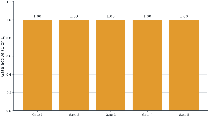
Tables round numerical values for reading; feasibility checks use the original solver values. Multiple optimal decisions may exist. Machine-readable result records the solver status and package versions. Figure-generation code is in figures/workbook.py.
12.5 Brief Discussion
The optimum uses 5 NOR gates and reproduces all four XOR truth-table rows in an independent circuit evaluation.
The MILP tests one topology against all input combinations simultaneously. A circuit that works for only one truth row is not a valid logical implementation. Allowing fan-out differs from a tree-only design and can change the gate count. Experiment: change the target to AND and compare the smallest circuit.